SYSTEM 1 REJUVENATION


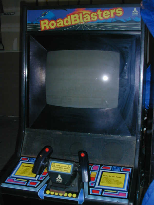
This has been sitting in storage for years taking a back seat to a lot of other projects...it's time has come.

Not easy to see here but besides mounting the pedal to the door there are a few other obvious problems to be corrected with the cabinet.
The left front foot was ripped off the bottom. The 25amp low voltage fuse was jumped out on the power supply chassis.
This cabinet was equipped with a fan, apparently all of them were not, the mounting holes visible. The rear cabinet power switch was removed .
There was also a crack in the frame above the coin door.
Note: the original 2 bolts on the lower right, this is the area the foot pedal was suppose to be mounted by using a template supplied adding 3 holes.
However, on this cabinet there is a factory 1 inch hole on the bottom under those bolts. It appears they made a change in the foot pedal afterwards.
This cabinet came equipped with a AC fan to help cool the game board area, but mostly to cool the ARIII power supply/Amp.
(so far all the ARIII boards I've seen show the boards get very hot, the solder side discolored from heat)
If you own one of these, probably a good idea to install a fan even if one was not originally installed.
I replaced the missing AC fan with one from Ebay straight from China. I enlarged the outer mounting holes to allow for easier installation.
Problem with it, though the specs indicated a lower than common noise level, it sounds like a jet aircraft.
Some research and I found another fan to replace it, not totally quiet but better, probably because it runs 1000 rpm slower.
Below are the fans, specs and location to get it.
This is the Fan
from China
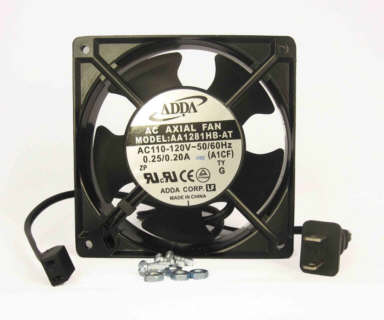
specifications
Voltage,
115 V AC
Frequency, 60Hz Current, 0.20 Amps
Speed, 2600 RPM at rated voltage and zero pressure
Flow (Max),
97 CFM Noise, 44.5 dBA at
rated voltage
and zero pressure, measured at 1 meter to side
Here is the Orion replacement I found.

From Markertek
Manufacturer: Orion
Fans
Item #: FAN-1 • MFG #: OA125AP-11-3TB
Orion OA125AP-11-3TB 4.7" Square 1600 RPM Muffin
Fan.
Quiet model (33dB). 1"
Deep.
One year warranty. Long life ball bearing
drives. Heavier duty aluminum die-cast housings. Glass reinforced
impellers.
Fan life is up to 70,000 hours. Meets UL/CSA requirements. Fans measure
115
Volts. Power Cord
Sold Separately.
This fan is much quieter than the previous one
List Price:$21.99
Back to the game

This is the altered front cabinet door. What the hole in the door edge was for? unknown.
The door lock for this door was intact at the top.
Here it begins
I took some time to address that foot pedal. I completely disassembled it, replaced the bushings, e- clips non slip surface, removed rust, painted and luricated it.
I am also creating a backer block for it to allow mounting it to the 2- factory screws in the cabinet.
I also added a rubber non skid mat to the bottom to protect the hardwood floor it will be sitting on when it's kit is being used.

The bushings are from a car parts supplier, they are .500 ID and used on clutch / brake assy's in older cars.


It useds a 5k pot , verified smooth operation.
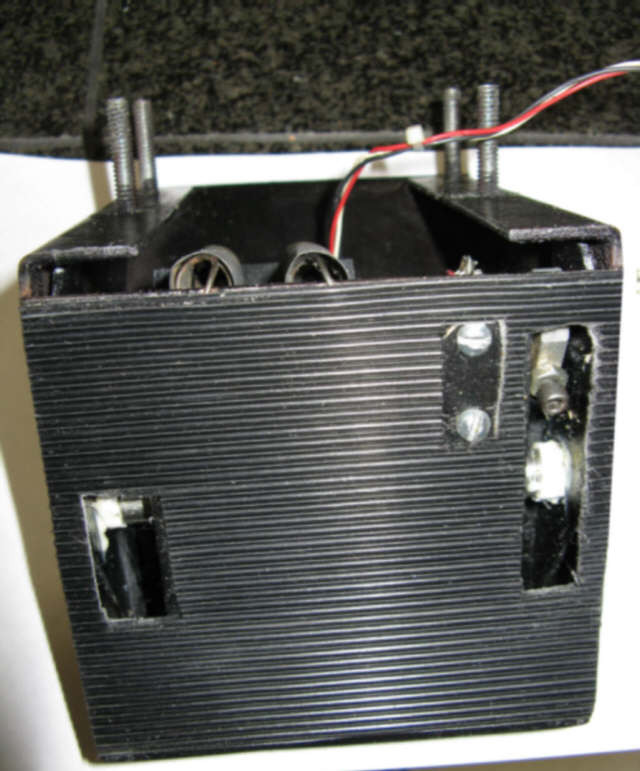
Here re-assembled (less spacer block to be added, mat added)

Here is the assy, the spacer is just a 4x6 drilled to accept the 4 bolts
It's counter sunk to accept the lock nuts. The 2 brackets are made out of thick aluminum. and secured to the block
The mounting uses the 2 holes left by the factory. Normally this cabinet, with road blasters installed would have a total of 5 holes here.
This cabinet has just the 2 holes and a large hole for the wiiring plug in the cabinet bottom.
Besides not wanting to add more holes to the cabinet, after I just closed a bunch, it was needed because of the cabinet height off the floor
Once rubber wheels were added to protect the hardwood floor it will sit on. So now the pedal assy sits on the floor on a rubber non skid pad.
The only negative is with the Road Blaster kit installed , the pedal must be removed to move the game.since it grips the floor.
Now on to the cabinet.

Here the side art is test fit to the cabinet for installation.
Note: the original art though not shown was full length. I had no idea there were different versions of side art used.
This version was purchased years ago anticipating it's future installation .. a surprise when opened , though different, I went ahead and used it.
It looks fine and my guess is that later versions of the system 1 cabinet used this.
Rubber Wheels have been installed for easy movement and protection of the hardwood floor it's going to call home.
All material in the cabinet was removed with the exception of the marquee (for now).
Epoxy filler was used to fill a hole drilled in the front used to secure the lock box.
This area will be recovered, along with the repaired front door.
The Road Blaster CP removed for future restoration.
A Marble Madness,CP and marquee will be installed initially.

Here surface imperfections are filled before art installation. The filler beyond the hole is removed as the final step.
I used Wellwood filler but added the addition of wood hardener to the surface using an artist brush.
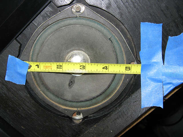
This photo is included to show there are variations of the cabinet.
This version uses 5 1/4" diagonal speakers. There are versions with smaller speakers.
The correct speakers are on order.
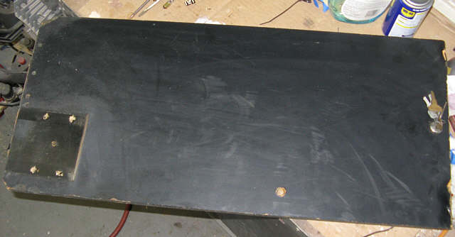
For some reason the Road Blaster kit installation in this cabinet included putting the pedal on the door
instead of on the right lower cabinet. The installation instructions clearly want it on the cabinet.
However only 2 holes were provided on the front filled with bolts. The install requires 5 holes.
The one in the center is suppose to be 1" across to allow the pedal plug to pass through. (they cut and spliced the wire)
This cabinet had what appears to be a factory 1 inch hole on the right cabinet bottom.
These holes will all be filled with epoxy wood filled and then new black vinyl over it.
I intend to just paint the back side.

Here the new side art has been installed, along with the front door repaired.
Because the cabinet is on angle it looks like the gap to the edge on the art is larger than it is, it's close to 1/4"
Also the coin door was repaired and repainted and new locks installed.
All things mention above were done.
It is fitted with a newly recovered marble madness CP along with new T Molding.
The speaker grill was stripped and repainted, though not initially noticeable there was some rust
starting under the paint in areas. As this is being written parts are on order to rebuild the 2 trackball assy's.
The rejuvenation of this cabinet also includes the cartridges and the control panels plus the foot pedal mentioned before.
On the road blasters this included working on control panel issues which including all 4 switches not working.
The switches used on the version of the yoke were common to some keyboards of that time.
There are 2 plastic pieces added to them to make up the button assy's. Each handle has 2 of them , fire and thumb.
These "keyboard" switches have long since been discontinued. There is at least one source as I write this.
However I decided to find out why they failed. Below are photos and info. to help in repairing the originals.
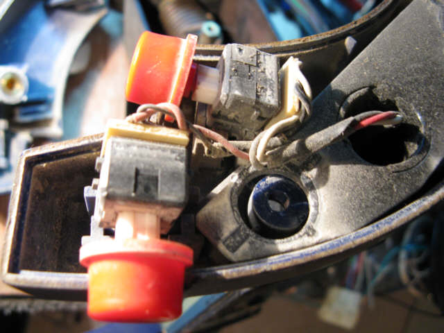
Here is what they look like inside the handle. Sitting on top of that white slide is an adapter to connect the button.

These are Omron B3G-S switches
The top cover is held on by 2 plastic clips (part of the top) on each side.

Here is what the bottom looks like after the small circuit board they are mounted to is removed.

Here the top cover has been removed along with the coil spring and white slide.
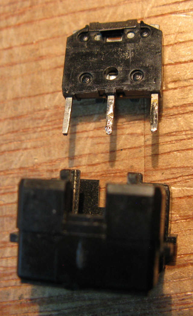
Here the switch assy is removed from the housing. Just press the pins on a flat surface and it slides out.
Those 4 circles on the back are what is holding the 2 halves together. Use a jewelers screwdriver and
spin it on top of those, effectively removing some plastic and weakening the joint.
This will make it easier to separate the halves.


When clean and adjusted, re-assemble, the 2 halves, just snap them together., then slide into housing.
Install spring clip, then coil spring, then white slide, finally snap top cover on.
Finally test switch operation before soldering it back to circuit board
THAT'S IT. THAT'S THE PROCESS.
All four switches now work perfectly.
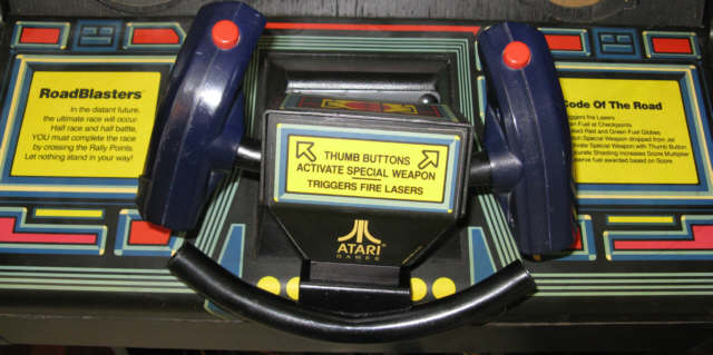
Here back together, normally centers, maybe the springs are a little weak.....next time.
There is also suppose to be caps on the pipe

INDIANA JONES CART
This details the work on the IJ board (cartridge)
This came up for sale in the middle of my System 1 project. It wasn't a game I had considered, but there it was.
So I took up the challenge to bring it back to life.
As can be seen here, there are a lot of open sockets, though a functional board does have some unused sockets.
This can be the most difficult type of project to tackle, often boards like this were used to supply parts for other repairs because it is damaged or
has a problem that could not be solved for some reason. Thankfully, this board shows no signs of physical damage.

2 custom chips are missing 1 SLAG (Syn Logic Array Graphics ) and 1 PROM.
Other missing parts, include 10 eproms, Speech, Sound Processor, Op Amp
Ok, First step to source all the missing parts. The eproms are available along with their software, the Slag chip is a tall order. As a matter of fact I didn't go ahead
with purchasing this board until I knew I could get this chip. It is a custom Atari IC .
The seller threw in a TI Speech chip, which goes into the board near the bottom edge on the right.
Steph from HobbyRoms in Canada wrote a replacement for missing the prom.
All the eproms on the board were tested, those that did not verify against the mame file dumps for this game were replaced.
A number of the eproms as found were in the wrong sockets. This board appears to be the latest version made, having the last software version.
This was one of the stumbling blocks on this, the Indiana Jones manual doesn't detail the version of software used on this board.
Possibly an official addendum was issued on this cartridge by Atari, however I searched and could not find one.
I needed to know which chip went into which socket, I figured it out.
I took it upon myself to add the info to the page in the ml showing which chips were used and the sockets they are installed in.
Here is a updated page 5-6 of the Indiana Jones manual

Click on it for full size
The last column of the program part numbers applies to this cartridge. It is included here for those that may run into the same issue.
(If someone reading this page has an official addendum from Atari about this change, please email me, I will add it to this page.)
Initially, after all the missing parts, those in the wrong sockets, and those that did not verify was corrected.
I got alternating messages of no cartridge and a blank screen.
Slide the test sw on and restarted the game, the test screen came up and showed no communication with the sound processor.
Turns out, this was because I ran out of 128k eproms and wrote the sound file to a 256k eprom. I realized I hadn't written the file correctly and re-wrote the chip.
Here is what I got, almost there!

Pulling one of the Slag chips changed the color but removed the lines.
I removed the entire set of slag chips (4), keeping then in the order removed.
A complete set of different slags was installed, pulled temporarily from a working Road Blasters cartridge.
The lines disappeared, and restored the color. Replacing that chip I had originally pulled (2nd) was the fix.
Here is the current screen output.

Below all missing, incorrect placed, or corrupted parts replaced.
Here is the working board as it stands
 .
. A total of 18 eproms were installed, plus the rest of the parts missing, detailed before.
The remaining empty sockets, normal for this cartridge. The board was designed to hold 128K or 256K eproms.
To put together the complete kit to run this game, I need the CP completely populated with overlay and a marquee..
I found someone that has taken on the task of making reproduction control panels for system 1 games.
I was going to make the harness but another person has taken that one as well and does a good job making it.
That left the overlay, marquee , buttons and the big one the Atari Logo Stick.
Reproductions of the art is on order. That was easy, but.....that stick is a tough one. Not as difficult to find as a Pack Rat Stick but not easy.
I found one, turned out though dirty to be in great shape, just needed a little tlc.
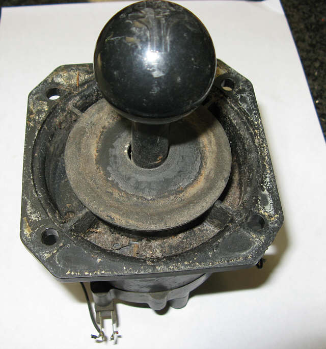
It was obviously transferred to another game from it's Atari Life, as the wiring was soldered to it.
As a matter of fact removing the wiring and solder from the leaf switches probably took more time than anything else on reviving this.
All the solder needed to be completely gone so the new harness connectors could easily slide onto the leaf switches.
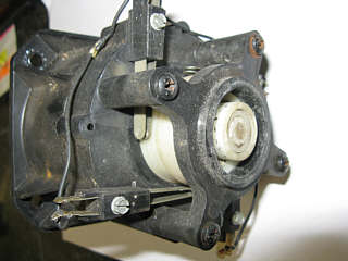

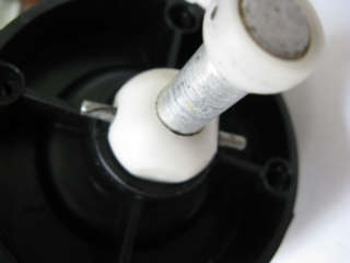

Here the Logo ball is polished

Here completely cleaned, re-assembled with the new harness and (new style micro sw_for now) buttons attached.
The leaf switches were cleaned, adjusted and the stick lubricated with lithium grease.
It's ready to go!
BTW the manual instructs that the stick should be lubricated every 3 months on location.
Did this ever happen, at any arcade?, I seriously doubt it.
The final piece to complete the panel is the panel itself.
Thanks for this goes to Ryan (Vegas12 on Klov) .
These panels are very high quality, photos are included below.
Tell Ryan I sent you if your looking for one.

Top
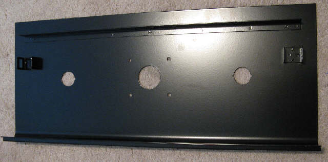
Bottom

Here covered in new overlay.

Here is the bottom side with "new" Leaf Sw push button Assy's as it originally came.
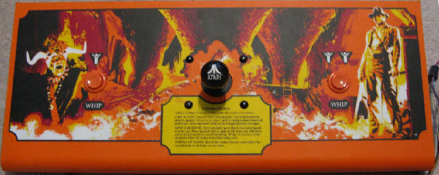
Final Assembly, buttons, wiring harness and restored stick come together.
Not sure these looked this good when they came from Atari.
Here is a little trick I used to make swapping out the "cartridges" for this cabinet easy.
On my System 1 cabinet the cartridge was plugged into the main board and then secured to mounting posts with 4- 6-32 3/4" screws in the corners.
Removing the cartridge required you to reach into the far reaches of the cabinet to get at 2 of the screws.
I changed that, with this.

There not easy to find but I came up with some.
It has been suggested that either as a aftermarket improvement or supplied by Atari, thumb screws were in fact used in system 1 cabinets.
If you know more about this, let me know.
These make pulling the board out and securing it a breeze. They are brass with a shoulder.
They need to be this length as the connectors on the main board require the cartridge to be mounted higher.
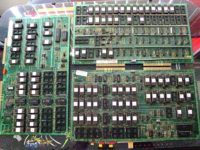
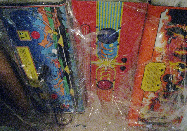
Here are the components for my System 1 kits, not shown is the Roadblasters as it's currently in the game cabinet.
Only one kit is missing Packrat. (Still looking)
