EXHIBIT SUPPLY DALE SIX SHOOTER GUN GAME
This page describes the restoration of a Exhibit Supply Dale Six Shooter Gun Game

Above from the Arcade1 book by
Richard Bueschel and Steve Gronowski

This page from Munves catalog
The game finally arrived . More information will be following
I have started to restore the art used inside the game. The rider clip art below is an example. There are 6 different riders on the "Ferris Wheel", more on that later.


Game Flyer


Here is the game before it was shipped


Ok, here it is a bit of a challenge.
The interior art needs to be re-created. The ferrous wheel target assy seems frozen, and is rusted.
It is missing both the back access door and the front door. It is also missing the 10 cent coin mechanism on the coin door, replaced by a button..
The ticket mechanism is also frozen, plus it lacks tickets.
The big one, the front art glass is cracked in half.
All of the above were known issues as purchased. There are some additional issues caused by the shipping company.
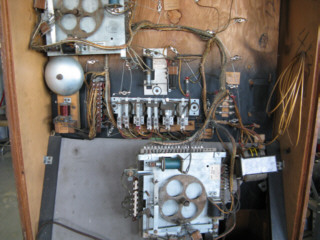
The game was bounced around enough that the power transformer broke free of the mounting board, in doing so struck the mirror and smashed it.
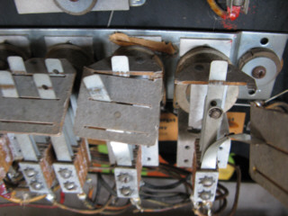
It also struck the relay strip assy, and broke a few relays. Finally the hit step unit came free of the board as well (the large unit seen on the upper right)
The transformer itself was damaged in the process, I believe repairable.
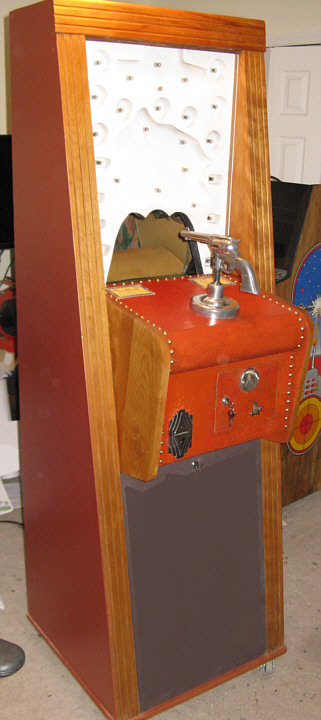
There are also some cabinet issues, unknown if they were there before shipping or not.
The photos below show some of the damage caused by the shipping company

Ok, let the fun begin.....
First, step was to remove the art glass and stabilize it. It was placed on a piece of plywood. I have a plan for this and will get into that later.
Next, I removed the electronics board which contains all the components of the game with the exception of 2 assemblies in the bottom cabinet and
the assemblies located under the front gun area, which includes the ticket mechanism.
(one additional component found eventually, more on this later)
I decided to make cabinet repairs first to stabilize the cabinet.

You'll notice that the front top trim has been removed. This is necessary to remove the lighting/electronics board behind the front art glass.
Normally that top trim is only removed to slide the art glass up, to remove it or to replace lamps behind it.
I have identified the correct original coin mechanism used in this game and located one (thanks Roger, Crow River trading)
I have been in contact with a few other owners of this game and with their help have started the process to recreate and restore missing and damaged artwork
With the help of those other owners mentioned above work is proceeding on the art restoration..it's time consuming..
I have completed the bottom scene along with the horses and riders as I write this.
I have started work to restore the rider ferris wheel assy itself. which includes the riders and horses.
I have chosen to make a complete new set of horses and riders but will retain the originals (in poor shape)
I am currently mounting the horses and riders on "chip board" , I also sprayed them with clear coat matte to protect them.
I re-designed they way they were put together.
Dale/Exhibit used a steel bar and riveted the art to it for horses , then they just shoved the mounting arm under the bar
This causes the horses to have a bow in the center. I also did not use rivets which can be seen from the front, instead made custom brackets and glued them to the chipboard. There are rivets (unseen) on the new revised mounting brackets, this to increase the thickness of the arm ends, this to allow space for the mounting
New art could just glued over the originals if the mountings were in good shape. Mine art not.
Cutting the chip board out is time consuming to match the shapes. (I used thicker material than used originally-twice as thick)
Probably should have done more research on chip board densities and available thickness
I have the original cardboard for the bottom art but will need to address the top side, since that art sagged in the middle.
It's interesting that they added a piece to the center of the top art to reduce the view to the rider ferris wheel.
Not sure if this was an original over sight or it was intentional?
I have my motor fully operational and restored, as I write this. The motor has been completely disassembled the commutator cleaned , new brushes installed, and the reduction gearbox cleaned and re-lubricated.
Here is the change I made to the new set of riders/horses.
I used aluminum, easier to work and doesn't rust like the originals did on mine.

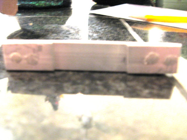
un-drilled yet

Here a restored rider and horse on it's control arm
One of the advantages of doing the mounting this way is I can adjust the horse to rider for the best look than glue and clamp in place.
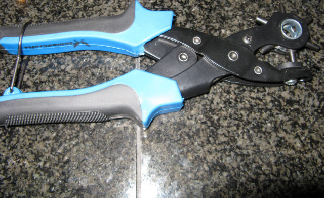
This is what I used to punch the rider mounting holes in the chip board (normally for leather)
They were then glued to a piece of aluminum and holes drilled through the chip board holes to allow mounting by screws
Chip board doesn't drill well, which is why the punch was used to create a clean hole.
Here is one of my original horses


The original riders / horses will be saved with the game
Here is a restored "upgraded" rider assy.
The bowing in the center and rivets have been removed for a better look
The riders and horses have been mounted to a material about twice the thickness and strength of the originals


Here is the horse/rider "Ferris Wheel" ready for installation in the cabinet.
The object on the left is the "Timer Unit" A little misleading as it controls both the number of shots and the speed of the Ferris Wheel which increases play difficulty.
The large resister on the edge is a 50 watt 100 ohm wire wound resister, tapped for 25 ohm and 75 ohm connection points.
Of note is when testing it, it was determined that the 75 ohm connection point was open. This because the contact point and contact bracket had rust on it..


These 2 points were cleaned. the bracket remounted and set for 75 ohms
One additional electronic problem was found
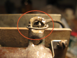
This connection was barely connected when it was made and had since become lose (It was re-soldered)
Finally the adjustable pins and sockets were cleaned.
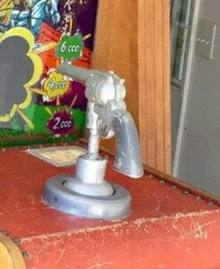

On the left shows the gun assy as purchased on the right all (original paint) removed and polished
Instead of re-painting it I may leave it polished, it looks much more impressive this way.
The 2 wires that exit the bottom of assy are for the trigger switch, which in this case needs to be adjusted / cleaned
The arm at the bottom has the spring loaded wipers that make contact with the biscuit assy (contact board).
There are no wires needed for the wipers themselves as it uses the metal of the assy to compete the other side of the circuit
There is a slight bend on that arm, it will be straightened so the contact springs make perfect contact on the biscuit board.
Not shown is the kicker solenoid, or biscuit contact board which mounts to the bottom of this
BTW the kicker solenoid uses full AC voltage as does the ticket mechanism solenoid. All such AC line connections are painted red to alert the servicing person.

Trigger Switch CR1070C103C3 ME/GE

This is a photo of a real Colt Frontier Six Shooter
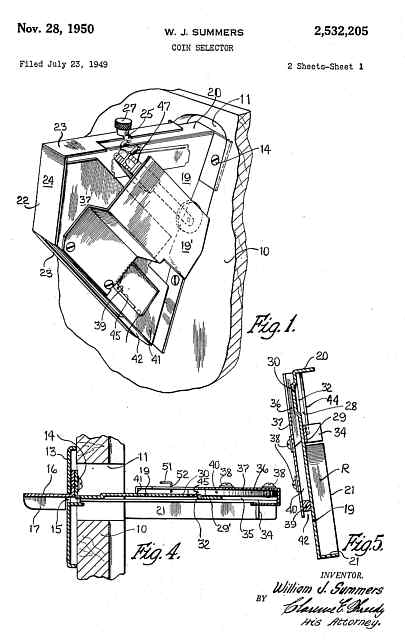
Patent drawing for the coin mechanism used in the Exhibit Supply Dale Six Shooter
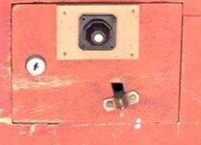
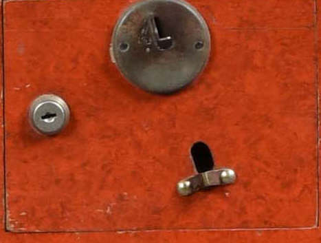
Door on
my game
Correct door
Mine is missing the correct coin
mechanism replaced by a push button to start the game. This will be
removed and the correct coin gear restored
A lot of these doors are missing from surviving games as they are not hinged but are designed with contacts so there is no hard wiring and they just lift off.


A lot of these doors are missing from surviving games as they are not hinged but are designed with contacts so there is no hard wiring and they just lift off.


This is the 10 cent United
coin mechanism used
This is the unusual coin switch
used by the united coin mechanism
Notice how the trim piece slot is on angle, it has to be that way so the coin stays on the ramp to the switch.
Notice how the trim piece slot is on angle, it has to be that way so the coin stays on the ramp to the switch.

These are the
correct type of bulbs for the bottom cabinet area.
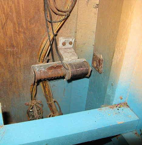

Before
Restored solenoid,
re-mounted on cabinet back
It turns out. it is on the wiring diagram, but disguised a bit, as I suspected, it is part of the "kicker" ct. called "kicker delayed relay" circuit
I think the gun shot solenoid is engaged ahead of the kicker solenoid by a slight delay making the shooting more realistic.
It is located behind a shield that obscures the view of this area when the player is viewing the game images, by the games mirror.
(see it above showing the clamping of the cabinet, it's the tan cover in the back)
What is it?, it is what makes the "gun shot" sound. It strikes the outer cabinet and is pretty loud, I tested it.
Combined with the gun kicker solenoid it completes the effect of shooting at the target
(Please if your reading this and have the actual schematic for this game (not cabinet wiring) please contact me)
(I would be interested in seeing any one of the 3 Dale Exhibit gun game schematics in this series)

More to come
NEWS: I will be offering reproduction "skill" tickets in the near future.
If you have one of the Dale games that uses these special full hole tickets and are interested contact me.
The tickets will be on a 1000 pc roll
The holes in these tickets are used to dispense the tickets versus newer styles that use 1/2 holes on the edge to be read by a sensor

New tickets being developed...contact me
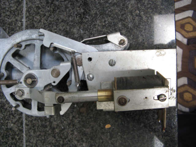
This is the unique ticket mechanism used

Though this game was introduced as a 5c game, not sure it was actually sold with 5c coin gear.
Most surviving games have 10c coin gear. It appears very early it was changed to 10c
Mine has 10c coin gear , which is reflected in the left instruction label. Both labels have been restored.


Here shows some of the bottom restored
art in place.
Replaced mirror, repaired xfmr & relays plus
restored step ups
The arms holding the riders are not seen
when viewed through the glass
and mirror.
The mechanism is obscured from view by the upper artwork , not shown here. That upper art is barely seen, there is no lighting in that area.
The art was printed as a banner and then glued to illustration board. The riders and horses art is mounted to chip board
The art was created from original scans and photographs with additional help from other collectors. None of the original bottom art scene was left in my machine except for a few scraps.


Here as purchased Here with newly created replacment art scene and fully restored "ferris wheel"
Here is the NEW GlassThe mechanism is obscured from view by the upper artwork , not shown here. That upper art is barely seen, there is no lighting in that area.
The art was printed as a banner and then glued to illustration board. The riders and horses art is mounted to chip board
The art was created from original scans and photographs with additional help from other collectors. None of the original bottom art scene was left in my machine except for a few scraps.
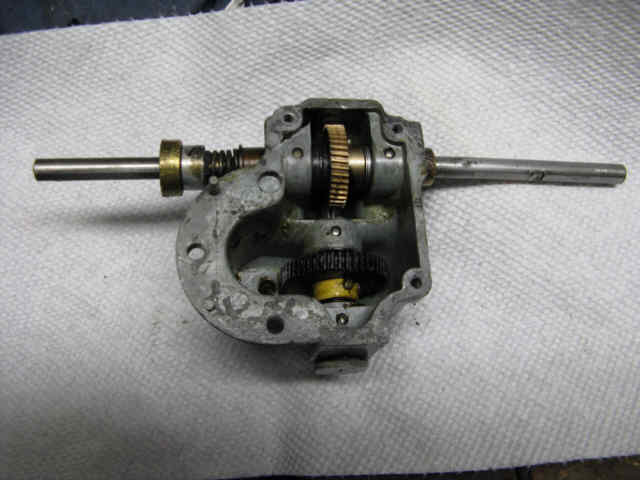
This is the "Ferris Wheel" motor assy,
disassembled, then cleaned, lubricated, brushes
replaced .and fnaly re-assembled.


These are the original motor brushes
Here a replacement
Replacements
found- ST-7F Carbon motor brush.
3/16" x 3/16" x 1 with 1-1/8" spring
(These were long, so the carbon had to be shortened to about 5/8")
(These were long, so the carbon had to be shortened to about 5/8")
Note: The originals were so worn that
the motor did not run at all, probably why this game was taken out of
service.


Here as purchased Here with newly created replacment art scene and fully restored "ferris wheel"


The new glass has arrived and looks great , more on this later. The game has all been restored and made fully operational.
On the sides and back cabinet is metallic copper paint as was originally on this one. I have no idea what the color of the front door was, as it was missing.
Wheels were also added to the bottom to make moving it easier, the front ones lock to help keep it in place when operating.
The lighting board holds 28 lamps, 19 #55 and 9 # 51. Except for 2 lamps, normally to replace the lamps in this board the front glass must be removed.
This is done by removing the top trim board held with 2 wing nuts in place. Note: when releasing that top trim the lighting board is just held in place
by 2 small brackets located on the back of it in the lower corners. Can the lighting board be removed, yes , but that is not needed to change lamps.
The center and top lights are continuously on when the game is plugged in, however the top 4, are powered through a flasher and once it heats
up they will start flashing together. The rest are scoring lights, and record shot count. They are reset off when a new game starts.
Note: The 2 lower lamps 1000 and 2000 are on slide brackets and can be changed by removing the front door and lowering the gun cabinet.
THE STORY OF THE FRONT GLASS
Before deciding to purchase this game and revive it I knew there was a big challenge. The front glass.
It was cracked in half. Unless I could find a NOS replacement, which was unlikely, restoring this game would not be possible.
I did some research to see if there was an alternative to having new glass silk screened as this would be a very expensive option.
I found BGresto.com, after looking over examples of what Steve had accomplished in the past on other game glass, and after few email exhanges I was convinced
this was the correct choice for my restoration of the SixShooter . To be clear, without BGresto, I would have passed on this game.
Go to BGresto.com for a clear explanation of the process and examples of the results acheived.
Judge here for yourself.


BEFORE- That crack runs from top to bottom,
glass in 2 pieces
HERE- After
restoration of the art and finally bonded to new glass
Contact BGresto.com if you need a replacement glass for your Exhibit Supply Six Shooter
Return to main (contact here)