One
of the first things I had to get a
handle on was the inoperative power switch. Once I pulled the amplifier
chassis to get a look at it, I found there were 2 issues.
First, the plastic button was snapped off at the point it was connected
to the switch and the second was the switch itself was jammed in the ON
state.
My guess is the button was broken in a attempt to get it to turn off.
When that failed and the button broke the previous owner installed a
line cord switch.
Originally, I thought I could just find a plastic button and attach
it to what was left of the original button.
That turned out to not be an option. The spring clip around the button
was all that was holding what was left of it together.
So ....I had to make a replacement button. The button is unusual. It
connects to the power switch off center.
Here is a sketch.
POWER
SWITCH BUTTON

I made it by turning a piece of hardwood, and using the original spring
clip. I painted it chrome, once done.
Now if I had a metal lathe, it would have been better out of aluminum
for example.


AMP &
TUNER
The mode selection rocker switches were in need of
attention.
Sometimes, placing the rocker in the tuner position resulted in
NO sound from the right channel. Along with the right channel
/speaker cutting out , sometimes it was low and distorted, sounding
like a blown speaker.
Cleaning the switches helped but there was still an issue. That turned
out to be the connection at the hinge. The hinges top and bottom
provide the speaker connections. The hinges had oxidized after 50 years
and non use. I assume if the speaker (doors) had been opened regularly
the connections would have been better. 0000 steel wool polished the
hinge pins up and between the clean switches and the hinges the sound
was now stable.
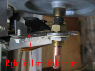
Time to move onto the missing light on the dial right side.
Getting at that one is a little tough on that chassis. It it behind the
tuning shaft weight and dial cord pulleys. The sockets had clips that
slid over mounting areas on the chassis. Once I had the bulb in my hand
I was able to ID it as #51. which is a 7.5v bulb. Of course I didn't
have any. Yes, I could have used something else but because they
used these it gives the dial a certain intensity on the 6v line plus
they would last longer than 6v bulbs as well.
Once I had the bulbs, I changed both of them.

To help in cleaning the unit and to gain better access I removed the
front panel from the cabinet, though it doesn't need to be removed.
It's held on by 4 screws and washers on each end of the panel
accessible from the back.
All the knobs must be removed, along with the nut on the tuning shaft.
The chassis screws are 1/4" , I think there were 6 of them holding
both chassis units to the front along with the tuning shaft nut I
mentioned.
The power switch issue, which probably caused the demise of the knob
was caused by the external case of the switch oxidizing.
This caused the locking / release arm on the switch case to "hang-up"
in one direction not allowing it to release. This effectively kept the
unit locked in the on state.
Cleaning and polishing the switch case along with a lite lubricant
allowed the locking arm to work correctly again.
Once the cabinet interior was clean in the area where the chassis units
mount
they were returned and secured in place. Installing the "new" knob for
the amp before hand.
Fortunately the amp and tuner work so nothing was really done to
them, other than trimming some component leads on the amp to help in
gaining
access to the mounting screws for that chassis.
TURNTABLE
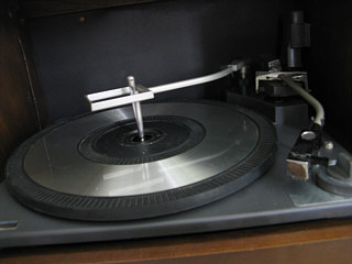
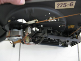
The turntable is a Ge 225-6. The
previous owner had played it for me, though not long enough to
recognize that
the
speed was changing.
I suspected the idler wheel. I also noticed that the stylus appeared to
be the original, clearly marked GE.
I decided to dismount the turntable from the cabinet. First to gain
access to the area under it for cleaning but also to check the
condition of the mechanism.
It's a little tricky to get it out.
It has what are pretty standard clips on the lock down screws.
Those clips can pivot to a straight up or horizontal position. In the
straight up vertical position they can be pulled out of the pre drilled
cabinet holes. When snapped into the horizontal position the screw can
not pass through the hole it's in.
It also has large wooden washers with a flat edge held above the clips.
The front washer needs to be rotated in a direction to clear the
cabinet on that hole. The front one (right-front) is slotted , The rear
left is not and it's position does not matter. That other washer will
have to be removed when the screw post clip is
snapped into the upright position.
There is also a holding clip on the front left turntable spring. that
spring must be free of it to remove the table.
Finally, once the turntable is lifted up, the wires need to be
disconnected to avoid damaging them. The audio cables are toward the
back and the power connector is toward the front.
They are short so care must be taken to not damage them. Also the
turntable once dismounted will be close to the back compartment area
and can damage the wood there.
To gain access to the idler, remove the spring clip ("C" clip) on the
spindle. It turned out the idler looked to be in good shape on
mine.
Smoke and age had given it's surface a smooth glaze like appearance.
Alcohol and a Q tip and some scrubbing restored the surface and gave it
some "grab".
Once reassembled into he case and tested it proved all that was needed.
I ordered a replacement stylus. It came and I went to change it. It
turns out this cartridge C650 has a clip to hold the needle in place.
So...you can't just pull it down and forward to get it out as is
normally the case on this type of cartridge.
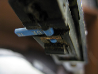
The plastic U shaped clip on the cartridge must be moved out of the way
to install a new stylus and remove the old one and then put back.
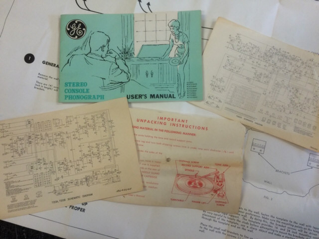
These drawings below are from the original owners booklet


I suggest just tilting the clip forward after gently releasing the clip
ends. This plastic is tiny (see actual cartridge photo) and 50+
years old. In the photo it has been pulled down and tilted forward.
Note: Someone said their cartridge was missing the "bump" near the
model#, that is rubber glued in place to help protect the stylus, it's
missing on some C650's. It will not effect it's operation if missing,
not sure how effective it
was. As you see in the original drawings it's not shown.
A little lubriplate on some of the moving linkages, record hold down
arm etc. and that's it.
The above restored the table along with cleaning to remove 50 years of
smoke damage.
Extra Tech Tip
Once the turntable was in use (unit hung on the wall) I noticed
some excessive noise from the motor , this noise picked up by the
cartridge while playing.
I dismounted the turntable to investigate. I removed the motor bearing
cap (2 screws), and the armature. I found there was some rust on the
armature. I removed the rust with 400 paper and 0000 steel wool. I put
a coating of oil on the armature surface and bearings and
re-assembled the motor. All noise gone!
There are 2 nuts on the bearing cap screws, used to lock them in place,
they will come loose, be sure to put them back.
SPEAKERS
& CABINET
The finish on the cabinet was "perked up" with some new stain and oil
rubbed finish.
The speaker grill has proven to be a challenge. Trying to find
replacement grill material that mimics the original has so far not
happened.
I'm hoping, in posting this on my projects page, someone will step
forward with a source for a similar material.
Here is what it's suppose to look like, with a dime on it for reference
for the weave size.

The area near the edge, where the dime is represents the most accurate
original color.
Looking at the photo at the page start shows how much the fabric faded
and was damaged by cigarette smoke.
To temporarily finish it I chose to use cloth I had laying around,
(black)- to be used on
the
outside , until I can find the right material... I left the original
material on
what is the front of the speakers which face the cabinet when closed. I
think it looks pretty
good in black. But I am still looking for a match for the
original speaker fabric.
Here is what it looks like now, until I find that fabric.


Not only does it look good, but it sounds good too.
I read on one of the forum sites someone claim these have the same
sound quality as the portable plastic GE's of that time. They do not.
The amp uses TO3 style outputs for example.
Though the turntable uses a ceramic cartridge, it still sounds pretty
impressive. The stylus pressure is adjustable 2.5-5 grams.
More info will follow:
Some info. detailed below
Besides the grill cloth, I'm looking for a original power button, this
from Nos or a parts unit.
If your reading this and have a TU20A parts unit , with a power button,
contact me.
Here is some additional: NEW INFO.


These are the original wall brackets to hang the stereo. They are
made from aluminum. These are the
original rca style patch cords to extend the speakers.
Dimensions are shown. They are approx. 1/16" thick. Except at the
bend.
Sockets to use them
are on the bottom surface of each speaker.
Below
are recently found Porta-Fi components. These would not have been the
units offered with the above stereo. They came later but are
functionally equivalent.
These were offered with or incorporated in newer models. Other than an
ac adapter I will
construct to use the prewired cheater cord installed in my
RC6731BWD
cabinet, the solid state transmitter
(SP66) should mount directly in
the area meant for the tube transmitter SP30.
NEW!
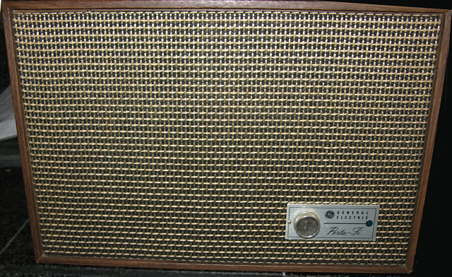
Though there is no model label
on this, I believe it is SP15, it is a tube based receiver version


It uses an unusual lamp.
(#15?)
This is the inside of the SP15, interesting how the componets were
combined as a set (sp66,sp15) , one solid
state and the other tube based.
These were factory supplied with a later console unit.
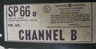


This is the solid state Sp66g . Though as you see there are both
left & right inputs, it's mono. The last photo shows the
audio level adjustment.
There turned out to be a few issues with this, first the 1/2 amp
pigtail fuse was blown. The repair, years before was to install a clip
lead across it.
I found out why the tech. made this repair, still no excuse. The audio
input jacks and the ac socket are riveted to the case. There is one
screw holding the board, on one side, the other side is held
by bends in the side cabinet. In order to get to the board bottom side,
the screw needs to be removed, the wires unsoldered from the rca
sockets and the socket posts moved out of the way. Bottom line, it's
tough to get it
apart.
It is possible after doing these things to open the case sides far
enough by bending them to allow the board to slide free and be flipped
over.
Once this was done I removed the blown fuse, and found it was loose
anyway, the leads having worked the solder loose holding them.
I also found the filter cap installed next to it was also not soldered
any longer.
I took the opportunity to inspect the 50 + year old board for other
issues. I found the the tunable coil connections were a bit
questionable, so they were resoldered as well.
It was re-assembled and tested. A slight re-tuning was needed as
well.
Next job, was to create a adapter plug/socket to allow the
standard AC plug on the SP66 to mate with the cheater cord in the
stereo.
This was done to maintain the original wiring in the stereo.


Here a cheater style socket was soldered to a standard 3 prong ac
adapter.
Doing it this way will allow the the SP66 to just plug right in.
Though not shown here, the mounting "wings" at each side were removed
since the cabinet mounted cheater cord is vertical.
Here it is installed in the RC6731bwd
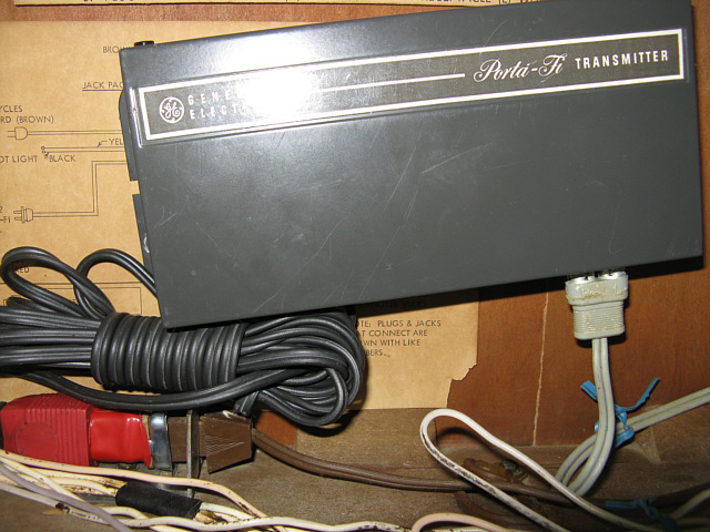
It's tilted because the older tube version of the transmitter is longer
and would reach the second pre-installed mounting post.
Note: the adapter installed to allow the standard attached ac cord of
the Sp66 to be used without any alterations of either unit.
PORTA-FI OPERATION
This system seems to work well when it's on the same
branch of the homes AC. When on another branch, it picks up noise.
Not sure if a filter of some sort would work without eliminating
the signal imposed on the line. (300kc Fm?)
If anyone knows?, was anything effective in reducing noise
picked up on this system, email me.
TIPS
FOR BETTER OPERATION
When it's on the same AC circuit there is absolutely no noise at all
and it
sounds great.
Additional Information- Besides being on the same branch of the AC in
the home or the same circuit, there should be NO switching power
supplies present.
Switching power supplies did not exist in 1965. These supplies are
used in many if not most ac adapters, to eliminate the need for a power
transformer.
If such a supply is used on the same ac circuit as the
Porta-Fi, the
noise generated from it will drown out the music transmitted.
From what I've been told this is similar to what happens to signals
transmitted on the X10 remote operation system.
The fix, remove those supplies, or unplug them when using the Porta-Fi.
A transformer based adapter could replace the offending adapters as
well.
Switching power supplies are also incorporated in products as well,
these may also interfere.
WANTED
TO COMPLETE THIS PROJECT
Speaker Grill Cloth - original or a close match- see photo on page
above.
Original Power Button- Does not have to be from this exact model.
Should have been used in a number of different units around 1965 (from
a parts unit or nos)
FOUND -A Porta-Fi
transmitter-
Model
SP66 (the transmitter available at the time this was sold
was SP30) Would be interested in finding a SP30 also.
FOUND -A Porta-Fi
Speaker-
Model SP15
There are a number of different models of
this as well, again I would like to find a solid state version. These
show up
regularly on ebay, so I should be able to find one. The SP15 is a
tube version. (SEE ABOVE)
INFO WANTED
There is a model of this
stereo
almost identical in configuration with large chrome rocker switches and
smaller black rockers to select functions, that may have had
Porta-Fi incorporated. Instead of using an external speaker, one of the
removable speakers was equipped with a porta-fi receiver.
Looking for info on it. If you have one, or know of this model, please
share the info. Thanks.


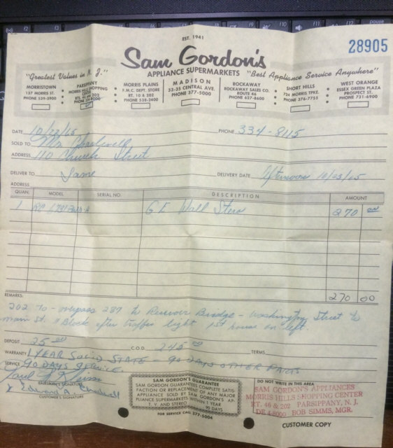



 Though there is no model label
on this, I believe it is SP15, it is a tube based receiver version
 It uses an unusual lamp.
(#15?)


