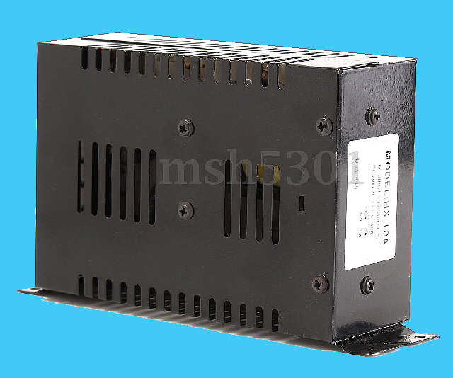
Inexpensive
Jamma Supply being sold on Ebay and Elsewhere
MODEL CP10A HX 10A
(with hidden issue)
They are offered with following
specs.
Features:
Universal
AC input/ Full range
Low
cost, high reliability
High
efficiency, low working temperature
Built-in
EMI filter
100%
full load burn-in test
Low
ripple & noise
Protections:
short circuit/overload/over voltage
Specifications:
DC
output: +5V/10A +12V/5A -5V/1A
Input
voltage: 100-220VAC
Input
frequency: 50-60Hz
Impulse
current: cold start, 20A at 115V, 40A at 230V
Overload
protection: 105%-150% hiccup mode, auto-recovery
Overvoltage
protection: 115%-135% rated output voltage
Set
up, rise, hold up time: 800ms, 50ms, 20ms/115VAC
Pressure:
-I/PO/P, I/PFG1.5KV/min
Working
temperature: 0-50 @100%, -10@80%, 60@60%
Safety
standards: Correspond to UL1950, EN60950, CB, CE
Interface
type: 8P/9.5mm pitch terminal block with cover
All appears to be accurate EXCEPT there is
NO -5V/1A
It was never implemented on the current version of this supply
The decision to remove this portion of the power supply was most
likely a cost cutting move.
They have sold a lot of them, and since most boards connected to this
will
not need the -5V the new owner will never know it's
missing, or
worse think it's failed at some point and buy another.
Most Jamma boards do not require -5V to function.
However there are some arcade boards that will not function without it.
Below are the details to correct the
omission of the -5v supply voltage so this can be used with any arcade
board it's needed for.
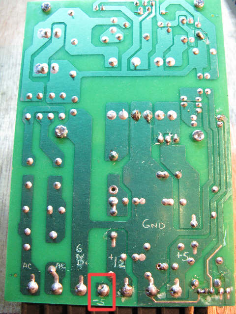
This is the board, solder side removed from the case. The terminal
circled is the -5V Screw post bottom.
As you can see : it is connected to nothing as sold
I've scribed on the board AC,Gnd, +12, +5, and -5 as marked on the
terminal strip label.
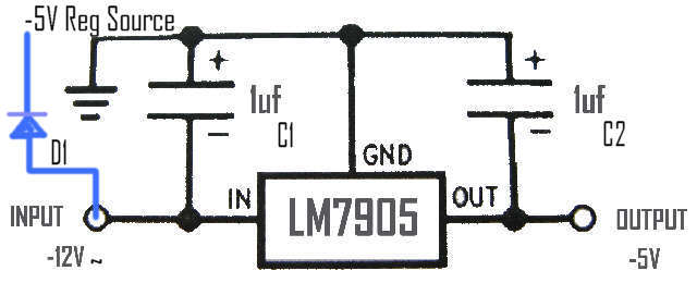
Above is what we need to add to the board to restore the missing
voltage.
I took the source input for the LM7905
from the +12v source before the
rectifier.
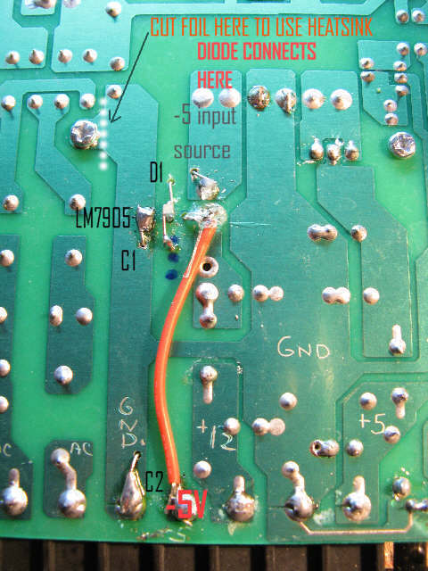
Here is where I placed the parts.

ORIGINAL MOD.
I used a small dremel drill bit to place the component holes in
positions that I thought worked best.
This photo shows the placement of the components, including the LM7905
-5V regulator, before change.
Change

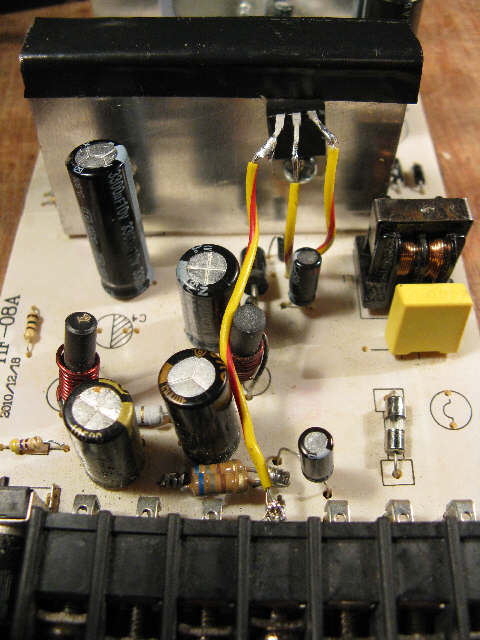 I found the regulator was getting
too hot when a game board needed the -5V, in one case it failed.
The regulator needs to be on the heatsink. Either use insulators to
mount it to the heatsink using the hole provided on the right. (best
solution)
Or cut the foil at the one
side of the heat sink mounting to isolate it from PCB ground and mount
the regualtor directly to it.
(see dotted line on board bottom).
Mount at hole on right, then wires can extend it's connections to the
points shown.
If mounted directly insulate the heatsink from the top case, and do not
secure it to the case top with original screws.
Mounting the regulator with insulators, eliminates the need for any
changes in case mounting or cutting PCB
Parts Needed
1pc.-2A pwr diode
2pc.-1uf electrolytic (any
)
1pc.- LM7905 (-5v regulator)
1pc.- wire jumper
1pc- mounting screw & nut (to secure regulator to heatsink
That did it. Now all the posts on
the CP10A provide the voltages as stated on the label!, including
-5V

